


Electronic Power Transformer
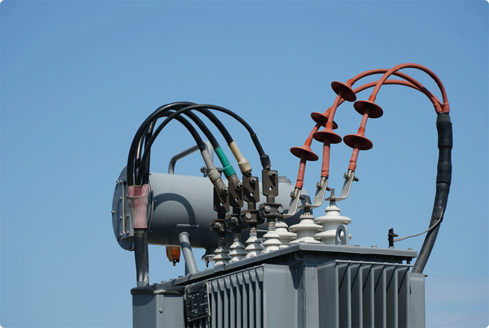
A Power Electronic Transformer (PET), also known as a Solid-State Transformer (SST), is a revolutionary device utilizing modern power electronics and control technologies to achieve the functions of a traditional line-frequency transformer (voltage transformation, galvanic isolation, energy transfer). It is not merely a simple replacement but offers significantly enhanced capabilities and flexibility.
Working Principle
The core principle of a PET is to replace the low-frequency (50/60Hz) electromagnetic induction of a conventional transformer with high-frequency power electronic conversion.
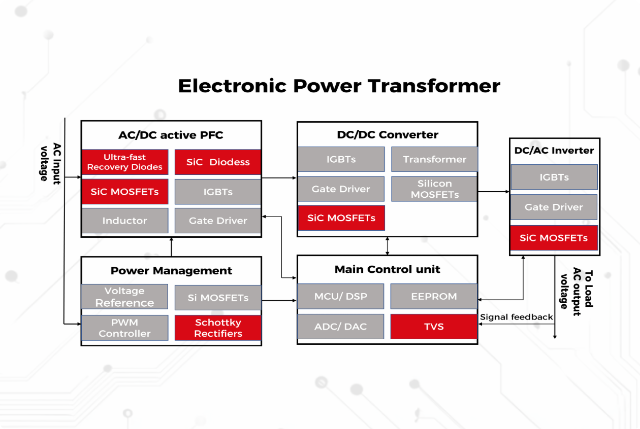
Input AC-to-DC Conversion (AC/DC): The PET first converts the incoming line-frequency AC (e.g., 10kV 50Hz) into DC power via a rectifier stage, typically composed of fully controllable semiconductors like IGBTs or SiC MOSFETs. This stage usually incorporates Power Factor Correction (PFC).
High-Frequency Isolation & DC/DC Conversion (DC/DC): The resulting DC is fed into a high-frequency DC/DC converter. The heart of this converter is a high-frequency transformer (operating typically in the kHz to MHz range, far higher than 50/60Hz). While utilizing electromagnetic induction for energy transfer, this transformer is drastically smaller and lighter than a line-frequency transformer of equivalent power (transformer volume scales roughly inversely with the square root of frequency).
DC-to-Output AC Conversion (DC/AC): The DC power, now isolated and voltage-transformed by the high-frequency transformer, is converted back to the required AC output voltage and frequency (e.g., 400V 50Hz) via an inverter stage (also using fully controllable devices) to supply the load. This inverter provides precise control over output voltage magnitude, frequency, and phase.
Control Core: A sophisticated digital control system (typically a DSP or FPGA) orchestrates all conversion stages. It is responsible for:
Stabilizing the output voltage.
Achieving input power factor correction.
Handling load variations and input voltage fluctuations.
Implementing fault protection (e.g., overcurrent, overvoltage, short circuit).
Performing advanced functions (e.g., reactive power compensation, harmonic suppression, bidirectional power flow control).
Key Differences vs. Conventional Transformer:
Frequency: Conventional transformers operate at line frequency; the core energy transfer within a PET occurs at high frequency.
Energy Form: Conventional transformers perform direct AC-AC transformation/isolation; PETs typically undergo a multi-stage conversion process: AC-DC, HFAC/DC-DC (isolation), DC-AC.
Predominant Architectures
Various PET architectures exist, but the three-stage conversion structure is currently the mainstream for research and applications, particularly in medium/high voltage domains:
Input Stage - AC/DC Conversion Stage (Rectifier Stage):
Function: Convert incoming line-frequency, high-voltage AC to stable DC while achieving high power factor and low input current harmonics.
Common Topologies: Multilevel converters (e.g., Cascaded H-Bridge, Modular Multilevel Converter - MMC), Vienna Rectifier, etc. These topologies handle high input voltages by reducing voltage stress on individual devices.
Key Focus: Efficiency, input power quality, controllability.
Isolation Stage - DC/DC Conversion Stage (Core Energy Transfer & Isolation):
Function: Provide galvanic isolation between input and output, and achieve voltage level transformation via the high-frequency transformer. This is the key stage enabling significant reductions in PET size and weight.
Common Topologies:
Dual Active Bridge (DAB): The most prevalent topology for research and applications, especially suitable for medium-power bidirectional power flow. Features H-bridges (or half-bridges) on both primary and secondary sides coupled via the HF transformer. Power transfer magnitude and direction are controlled by adjusting the phase shift angle between the bridges. Advantages include inherent soft-switching capability (improving efficiency), relatively simple control, and natural bidirectional power flow.
LLC Resonant Converter: Can achieve soft-switching under specific conditions, offering high efficiency. Typically better suited for unidirectional power flow or applications with narrow voltage regulation requirements; bidirectional control is more complex.
Others: Resonant converters, Phase-Shifted Full Bridge, etc.
Key Focus: High-frequency transformer design (efficiency, thermal management, insulation, parasitic parameters), implementation of soft-switching techniques (ZVS/ZCS) to maximize efficiency and power density, control strategies.
Output Stage - DC/AC Conversion Stage (Inverter Stage):
Function: Convert the isolated DC output from the DC/DC stage back to the required AC power (controllable voltage, frequency, phase number).
Common Topologies: Full-Bridge Inverter, T-Type Neutral-Point Clamped (NPC) Inverter (common for 400V AC output).
Key Focus: Output power quality (low THD), voltage regulation accuracy, dynamic response speed, capability to handle unbalanced and nonlinear loads.
Auxiliary & Control Unit:
Includes sensors (voltage, current, temperature), gate drivers, protection circuits, cooling system (air/liquid), and the core digital controller (DSP/FPGA/microcontroller).
Architectural Characteristics:
Modularity: Especially crucial for medium/high voltage, high-power applications (e.g., traction, smart grids), modular multilevel structures (MMC-based PET/SST) are often employed. Multiple power modules are connected in series and/or parallel, enhancing system voltage/power rating, redundancy, and reliability.
DC Link: The intermediate DC bus provides energy buffering and facilitates the straightforward integration of energy storage devices (e.g., batteries, supercapacitors) or renewable energy sources (e.g., PV, fuel cells).
Multi-Port Extensibility: The core PET architecture naturally supports multiple ports (e.g., AC ports at different voltage levels, DC ports), enabling the construction of future AC/DC hybrid microgrids and energy internet nodes.
Market Trends
PET/SST technology is experiencing rapid development with significant market potential, driven primarily by the following trends:
Renewable Energy Integration:
Wind/PV: PETs enable direct connection to medium-voltage DC collection grids, providing efficient, flexible power conversion, voltage matching, reactive power compensation, and harmonic filtering, enhancing renewable integration capability and grid stability.
Energy Storage Systems (ESS): PETs are ideal as the core of multi-port energy routers, efficiently connecting ESSs at different voltage levels to AC or DC grids.
Smart Grids / Active Distribution Networks:
Enhanced Power Quality: PETs enable real-time voltage regulation, reactive power compensation, and harmonic suppression, addressing issues like low voltage at line ends and voltage fluctuations.
Fault Management: Possess fault current limiting and rapid fault isolation capabilities, improving grid resilience and self-healing.
Flexible Grid Structuring: Support the construction and interconnection of AC/DC hybrid microgrids.
Digital Node: Serve as a physical data acquisition and control node within the smart grid.
Electric Vehicle (EV) Ultra-Fast charging:
High-Power Charging (HPC) Stations: PETs are the core technology enabling direct connection from medium-voltage grids (e.g., 10kV+) to power 350kW, even MW-level ultra-fast chargers. They significantly reduce size/weight, increase power density, and improve grid-side power quality.
Charging Hub Integration: Can simultaneously provide AC and DC charging ports while integrating storage and PV interfaces.
Traction Power Systems (Railway):
Next-Generation Locomotives/EMUs: PETs replace bulky line-frequency transformers, drastically reducing weight and volume, increasing power density and efficiency, and enabling efficient feedback of regenerative braking energy to the grid.
Railway Substations: Used in intelligent traction power supply networks to enhance power quality and supply flexibility.
Data Centers & Critical Load Power Supply:
Extremely high demands for power quality, reliability, and efficiency. PETs can provide high-quality, regulated output, seamless switching, and potentially simplify traditional UPS architectures.
Industrial Applications:
Powering power-quality-sensitive equipment (e.g., semiconductor manufacturing), retrofitting power systems for special loads (e.g., arc furnaces, induction heating).
Technology-Driven Trends:
Wide Bandgap Semiconductors (SiC/GaN): The core engine driving PET advancement. SiC and GaN devices offer higher switching frequencies, superior efficiency, higher operating temperatures, and smaller size, dramatically boosting PET power density, efficiency, and performance ceilings.
Advanced Topologies & Control Algorithms: Research focuses on more efficient, reliable, and cost-optimized converter topologies (e.g., improved MMC-based, hybrid) and advanced control strategies (e.g., Model Predictive Control - MPC, AI-optimized control) to handle complex operating conditions.
Integration & Modularity: Continued push for higher power density and lower costs through Multi-Chip Modules (MCMs), System-in-Package (SiP), etc.
Thermal Management: Efficient cooling solutions (e.g., direct liquid cooling) become critical as power density increases.
Standardization: Standardization of interfaces, communication protocols, and performance metrics is vital to accelerate market adoption.
Challenges:
Cost: Current costs are significantly higher than traditional transformers (primarily due to power semiconductors and high-frequency magnetics), which is the main barrier to large-scale commercialization. Costs are expected to decrease with technology maturation and volume production.
Reliability: Power electronic devices inherently have higher expected failure rates than electromagnetic components. Designing for high reliability requires redundancy techniques and predictive maintenance strategies.
High-Voltage, High-Power Devices: Performance, reliability, and driving/protection technologies for SiC devices (and packaging) above 10kV remain critical challenges.
Complexity & Control: Multi-stage conversion and multi-objective control strategies are inherently complex, demanding high-performance controllers.
The advantages of SMC
SMC, as a globally leading power semiconductor device manufacturer with nearly 30 years of history, can provide customers with the most advanced, efficient, and cost-effective third-generation silicon carbide MOSFETs and silicon carbide JBS diodes. In addition, SMC has unique experience in silicon-based power diode devices, and its best-selling high-power ultra-fast recovery diodes, high current Schottky diodes, and other products are highly praised by customers worldwide. SMC's power semiconductor devices can provide higher efficiency, better reliability, good delivery time, and competitive prices for your products. SMC's professional service team around the world allows you to experience the ultimate customer service experience and safeguard your product design.


 ������������Ʒ!


